How to install Nest thermostat on a Y plan heating system (UK)
In this post I will show you how to install Nest thermostat (3rd Gen) on one of the most popular heating plans in UK – Y plan. I have also created a video that you can see below with a full tutorial.
Y PLAN
First thing we need to do is to confirm your heating system is in fact a Y plan. At the heart of the Y plan system is a 3 port mid position valve.
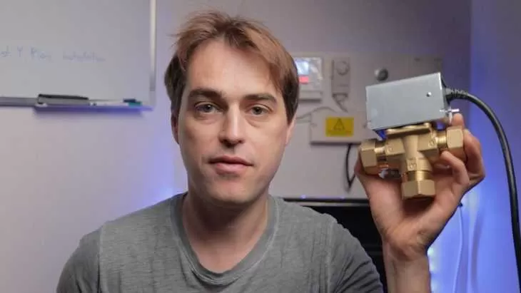
3 port mid position zone valve
It is used mostly on vented heating systems with hot water cylinder fed by a cold water storage cistern. The valve has 3 plumbing connections, hence the name Y plan, as it looks a bit like a letter Y. If you have one of those by your hot water cylinder and you also have a cold water storage cistern, usually in your loft then most likely you have a Y plan.
SCHEMATICS
Below you will find a full colour schematics for Nest installation on a Y plan heating system. It may be a good idea to print it out if you are planning on installing a Nest thermostat on a Y plan. Click on the picture below to get a full resolution Nest installation schematics.
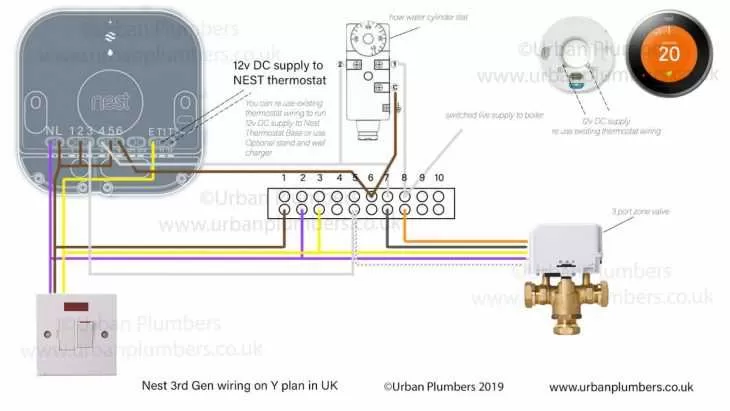
Nest thermostat Y plan wiring schematics
Remove programmer from the back plate. Usually it is held by 2 grab screws. There is a number of different programmers you’ll come across but the majority of them will share the same back plate.
On the back plate you should have following connections: N,L and 1,2,3,4
N,L – that is live supply to the programmer.
1 – HW off
2 – CH off
3 – HW on
4 – CH on
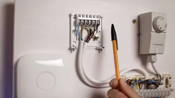
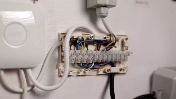
Existing programmer back plate with all wiring in place (N, L, HW off, HW on, CH on
You should have a total of 5 wires connected to the back plate: N, L, and terminals 1,3 and 4.
Take a note of where the wires go or take a picture of the back plate as you will need it for reference later. If there is more than 1 wire with the same colour – mark them with a ball pen or a marker before you remove the back plate to help with identification.
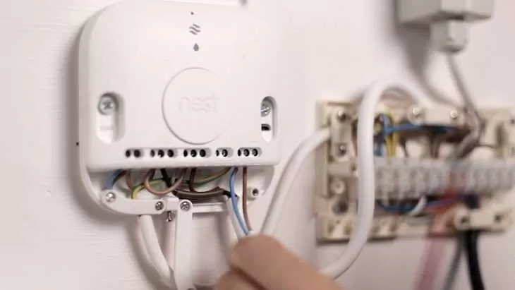
Remove back plate and install Nest Heat link. Heat link also has N and L connections plus 2 sets off connections: Heating is 1,2,3 and hot water is 4,5,6. CH operate as follows: 2 is common – this is where 230V permanent voltage goes – and it switched to 1 (for heating off) or to 3 (heating on). Whatever voltage is applied to terminal 2 is send to terminal 1 when heating is off or to terminal 3 when heating is on. We need to find a wire that was connected to the back plate of the old programmer to CH ON (terminal 4) and connect it to terminal 3 on the Nest Heat link.
HW operates in the same manner – 5 is common, 4 is HW off and 6 is HW on. Again, voltage is applied to terminal 5 is switched to terminal 4 for HW off and terminal 6 for HW on. In Y plan we will use both of those connections. It is simply just a matter of moving wires from the back plate terminal for HW OFF (terminal 1) to terminal 4 and HW ON (terminal 3) to terminal 6.
To sum it up it is simply is a matter of transferring wiring from the old back plate to Nest Heat link.
N to N
L to L
HW off (back plate terminal 1) to Nest terminal 4
HW on (back plate terminal 3) to Nest terminal 6
CH on (back plate terminal 4) to Nest terminal 3
Nest heatlink – all wires from existing programmer transfered to the heatlink
Once we’ve transferred wiring to the Nest Heat link from the back plate of the programmer it is time to run permanent live to commons. Commons are middle connections on the Nest Heat Link. For heating it is terminal 2 and for hot water terminal 5. Right now there is nothing supplied to the common connections so the system will not work. We have to supply permanent live to the common connections 2 and 5
One of the ways of doing it is to run a jumper wire from the Heat Link L terminal to common terminals.
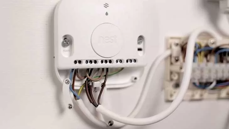
Nest heatlink with jumper wires (L to 2 and L to 5) installed
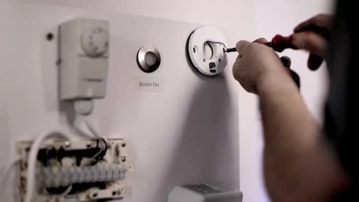
REMOVAL OF EXISTING THERMOSTAT AND INSTALLATION OF NEST THERMOSTAT IN IT’S PLACE
With heat link fully wired now it’s time to remove existing thermostat and install the Nest thermostat in it’s place. Nest thermostat connects to a back plate called nest base. It communicates with the heat link wirelessly but it still needs wiring for power supply. Nest runs on 12V DC and you have 2 options to run power to it. First option is to buy a nest stand with a wall charger for around £30.00 in the UK. If your existing thermostat is wireless and runs on batteries this is by far the easiest option. Run a micro USB cable through the stand to the base, tuck the cable in and fix base to the stand with 2 screws supplied with the stand. Plug the Power Supply in and you are ready to go.
If you find Nest stand and exposed wires not elegant enough there is a 2nd option. Simply re use existing thermostat wires to power up your nest. Remove existing thermostat, trace the wires back to the wiring center, disconnect the wires from the wiring center and use them to power up your nest with 12V DC supplied from the heat link. In most cases existing thermostat will be remote to the wiring center and you will have to use the multi meter to confirm you have identified the wiring correctly. If your Y plan is wired correctly you will have between 2 and 4 wires coming from the wiring center to the thermostat. We will disconnect all of them and only reuse 2 of them.
Why would you have more than 2 wires? The most common installation is a 2 wire one – common and call for heat on the thermostat going to wiring center but you can also have green and yellow going to earth and blue going to Neutral. For our installation it actually does not matter how many wires go to your thermostat as long as we have at least 2 wires. All we are doing is disconnecting them all at both ends and re using 2 of them to run 12V DC from the heat link to the Nest base. On the wiring centre 2 wires that we have to disconnect are: Heating ON from the heat link (in our case it is terminal 4 on the wiring centre) – disconnect the wire coming from the thermostat, not the heat link. And wire connected to the white wire of the zone valve. In our instance it is terminal 5. Keep white wire from the zone valve in and only remove the wire connected to it. If your existing thermostat has more connections – remove all the others too – such as neutral and Earth.
Quick word of warning! Make sure you identify the wiring correctly. All voltages in the wiring center are 230V AC and if you connect that to your Nest by mistake, well you have just burned £200 and you need to spend another £200 on a new Nest. So how do we make sure the wiring is identified correctly? Use your multimeter. Set it either Ohms or if your multimeter allows it, continuity testing preferably with sound indication. The way this usually works is: if there is continuity in the circuit (meaning wires are connected) there is a sound. If there is not continuity – there is no sound.
Grab those 2 wires that we just disconnected form the terminal 4 and 5 and connect crocodile clips to them or wrap them around the probes if you do not have crocodile clips. Now on the other end – existing thermostat side connect those wires together – Sound buzzing. Congratulations you have just confirmed it is the same wiring at both ends. Now connect 2 wires at Heat Link 12V DC terminals and connect the same colours at Nest base terminals 12v DV supply. For now leave the actual Nest thermostat alone and do not plug it into the Base as we will test nest base for 12V DC at a later stage.
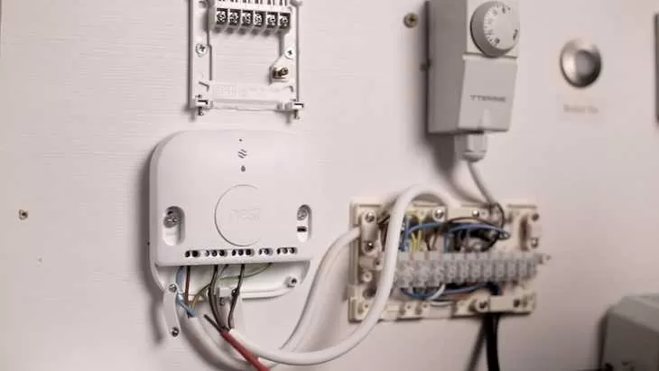
Nest thermostat base installation reusing eixsting thermostat wires for 12v DC supply to the base
Nest heatlink – connecting wires to T1 abd T2 for 12v DC supply to the base
There is one more step before the wiring is complete. Because we have removed the old thermostat – by doing so we have also removed a connection between terminal 4 and 5 on the wiring centre. If there is a call for heat from the Nest heat link a 230V will be applied to terminal 4 of the wiring centre – but if we look at it there is nothing else connected to it.
Call for heat from heatlink terminal 3 going to wiring center terminal 4 is not connected to anything. We need to move that wire (black here) to connect it with white wire from the zone valve (call for heat – heating) – that white wire is in terminal 5 of the wiring center.
This switched live from the Nest Heat link needs to connect to a white wire of the zone valve. All we have to do is to move call for heat from the Nest Heat link coming to the wiring centre to the white wire of the zone valve. In our case we have to move a wire from terminal 4 in the wiring centre to the terminal 5 where the white wire is. This completes the wiring installation.
SET UP AND TESTING
When it comes to testing your new Nest there are 2 main things you should be aware of. When testing hot water operation be aware that Nest 3rd generation has what is called: anti bacteria setting – which keeps hot water on for short periods of time even when the hot water program is off. This may confuse you at first as there may be a call for hot water although you set hot water to off on the thermostat. Check for the anti bacteria program symbol on the Nest thermostat to see if is is activated. It looks like this. (Small drop of water in a circile on the bottom of the Nest display)
Anti bacteria symbol displayed on the bottom of the Nest thermostat
If you see this symbol it means that Nest is sending a signal for hot water to be on. All you have to do is to simply wait for the program to finish. Another thing that can confuse your testing is anti cycling prevention setting on your boiler. What it means is that once the boiler is stopped after demand for heat (both hot water and heating) it will not start again for a set amount of time, usually between 5 and 20 minutes. This can again cause confusion when testing our circuit. To get around this problem you may have to turn the power off and on again between the tests if the boiler does not fire after call for heat is removed for the first time. For example: you test your heating – boiler fires up and all is fine. Then you turn the thermostat down and boiler stops. Now you turn the hot water program on – and nothing happens – boiler does not fire. It does not necessarily mean there is a problem with your Nest or wiring. I could be anti cycling prevention that stops the boiler from firing. Simply turn the power off and on again at the spur switch and try hot water again. If the boiler fires on hot water now – then all is good and as expected.
If you need your Nest installed by a Nest Pro installer you can contact me here: plumber Crystal Palace